Project Image Pool
There are 199 results.
Terms of use: The pictures on this site originate from the projects in the frame of the programmes City of Tomorrow, Building of Tomorrow and the IEA Research Cooperation. They may be used credited for non-commercial purposes under the Creative Commons License Attribution-NonCommercial (CC BY-NC).
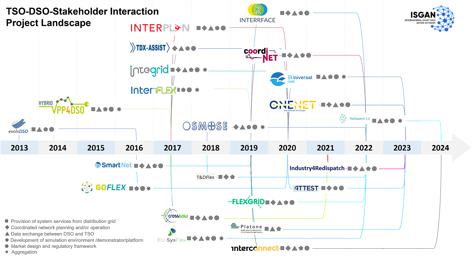
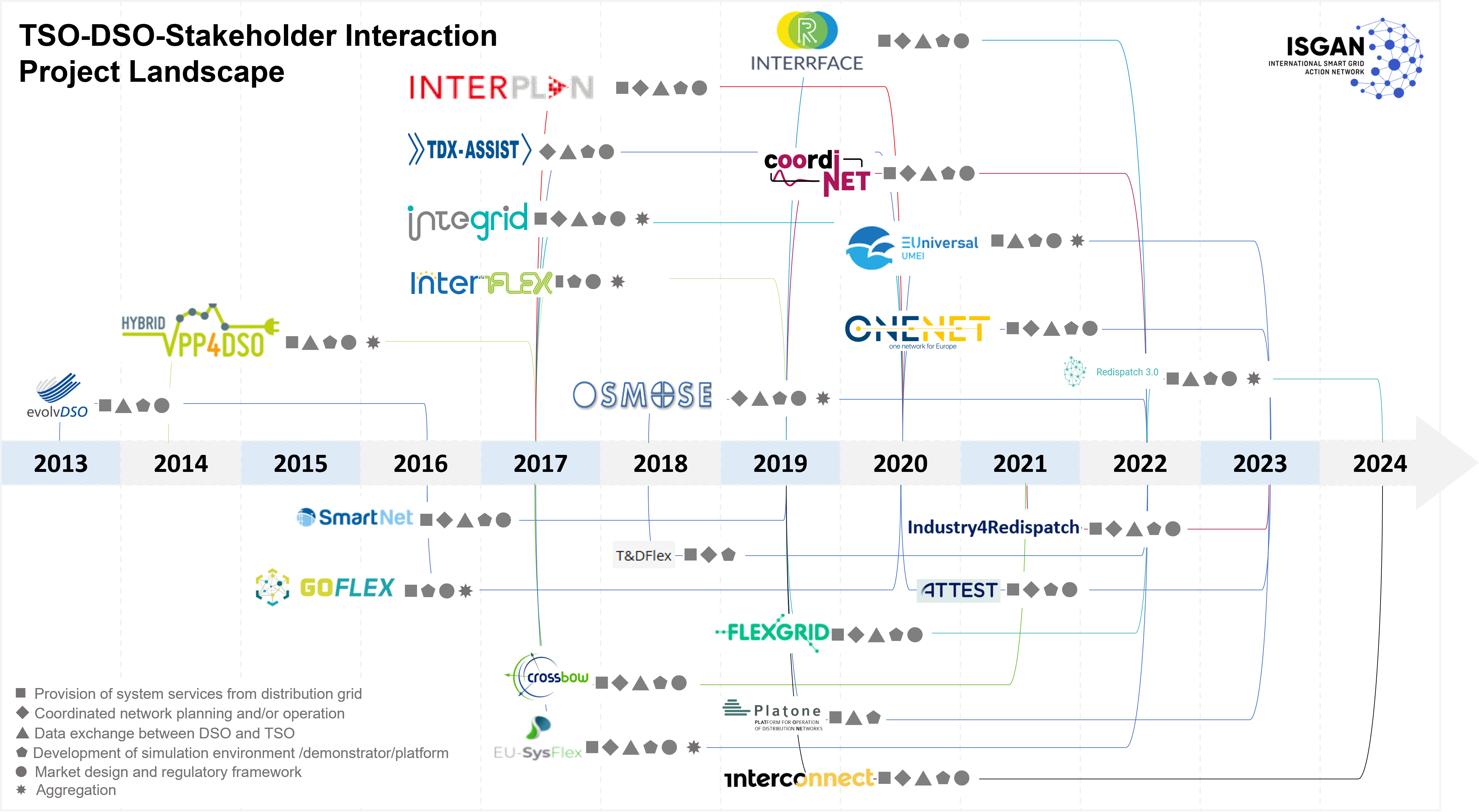
Overview of the ÜVB-VNB project landscape
Overview of the ÜVB-VNB project landscape which provides an overview of the international projects (2014-2024) which were evaluated and used for the report. Also indicated are the projects' respective focus areas
Copyright: Barbara Hernlder
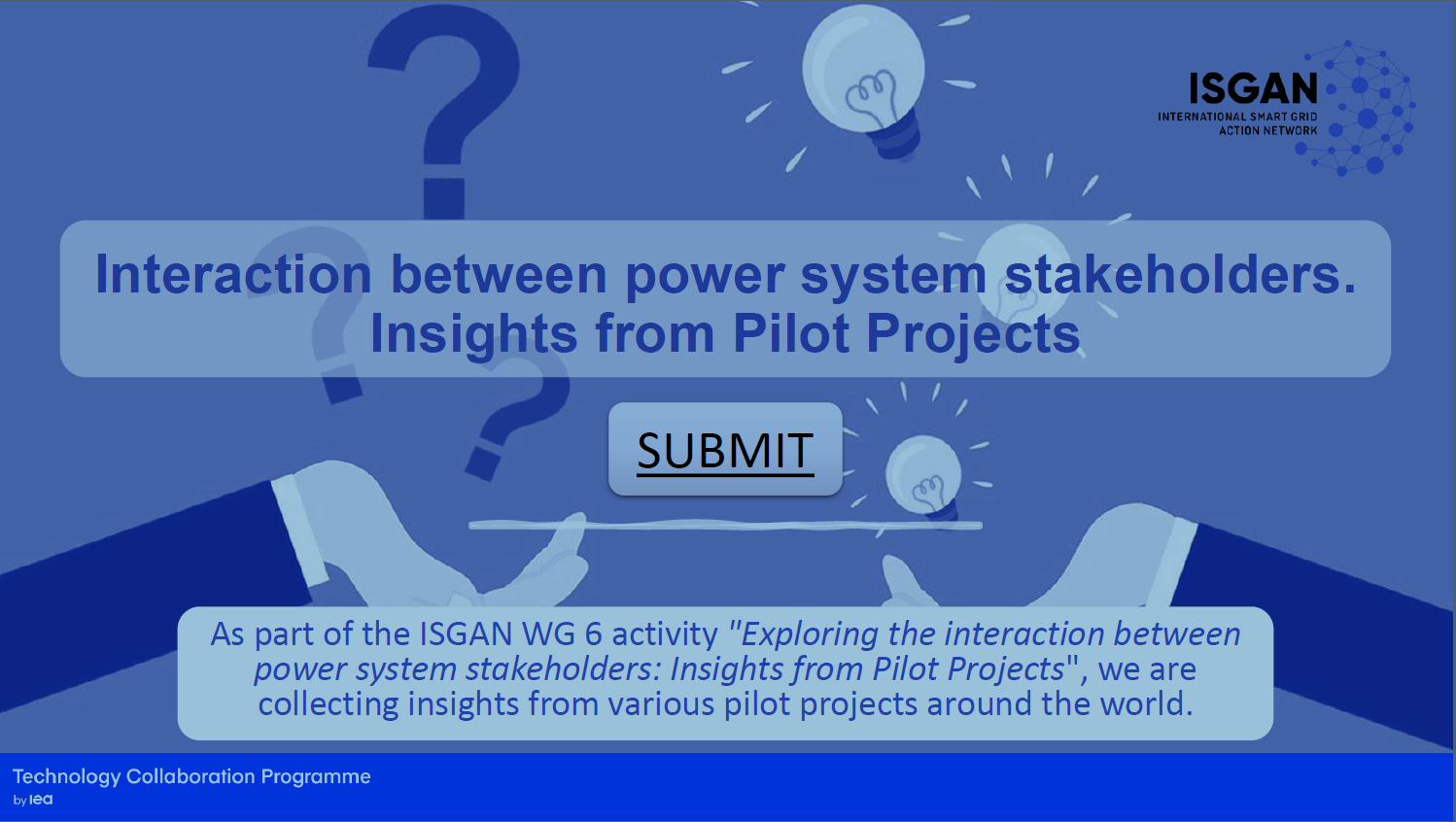
Example of a LinkedIn post for a survey
Example of a LinkedIn post for a survey which was conducted during the initial phase of the project
Copyright: Barbara Herndler
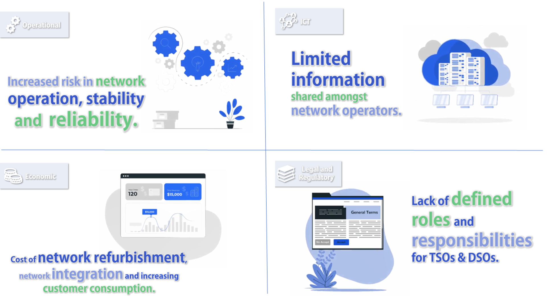
Key Challenges for Felxiblity usage
The figure shows challenges that arise in the use of flexibility. These relate to 4 dimensions: Operational, ICT technical, economic and regulatory challenges.
Copyright: AIT
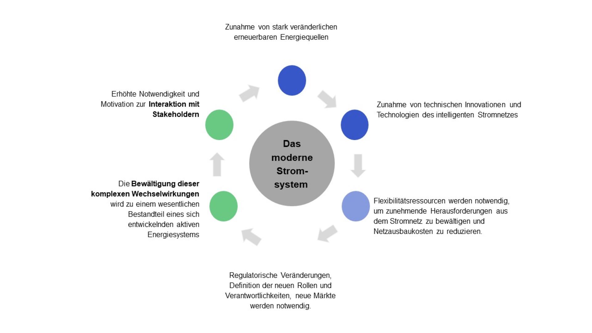
Paradigm shift in the power system
The paradigm shift in the power system and the new challenges for transmission and distribution system operators are presented.
Copyright: AIT
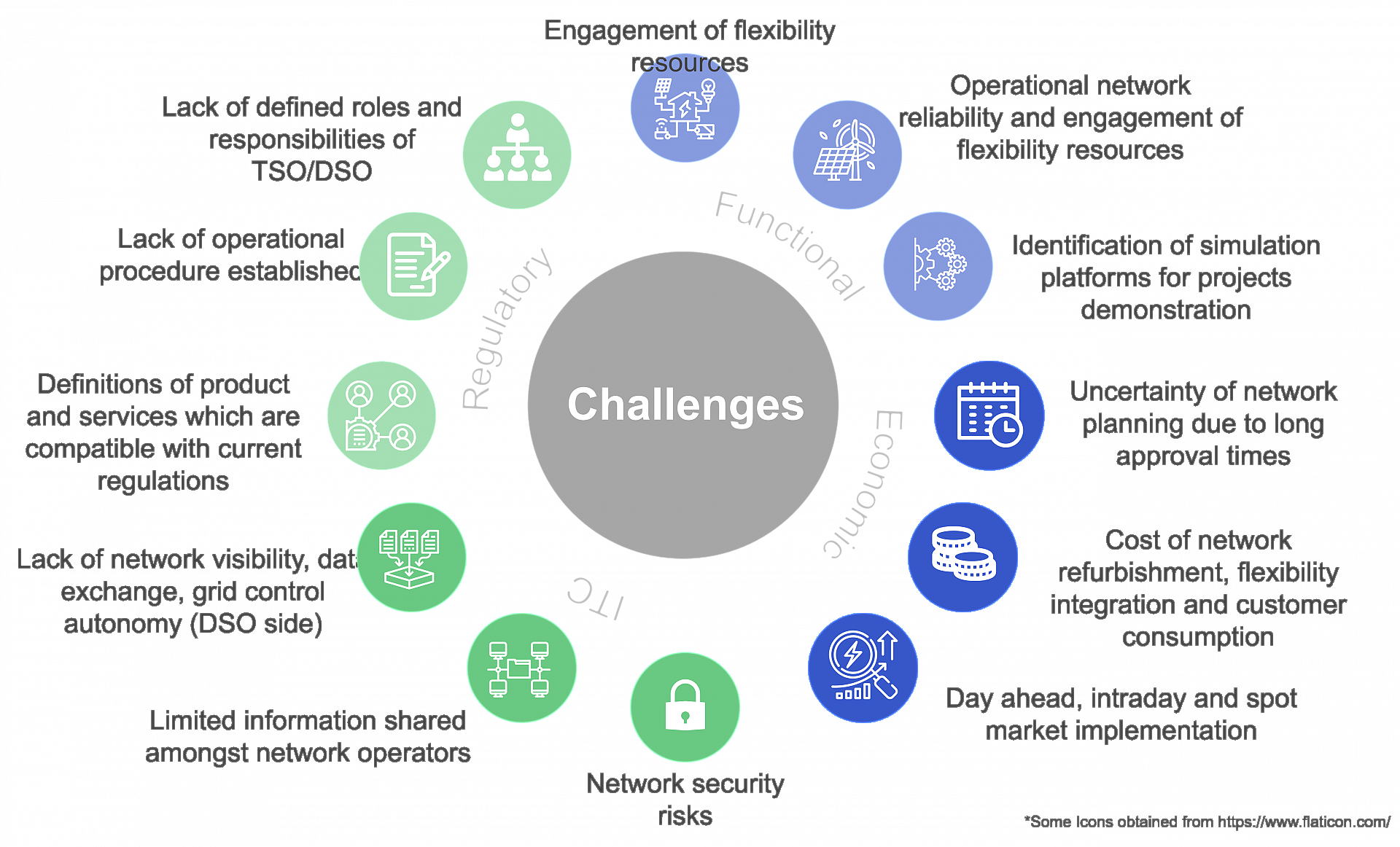
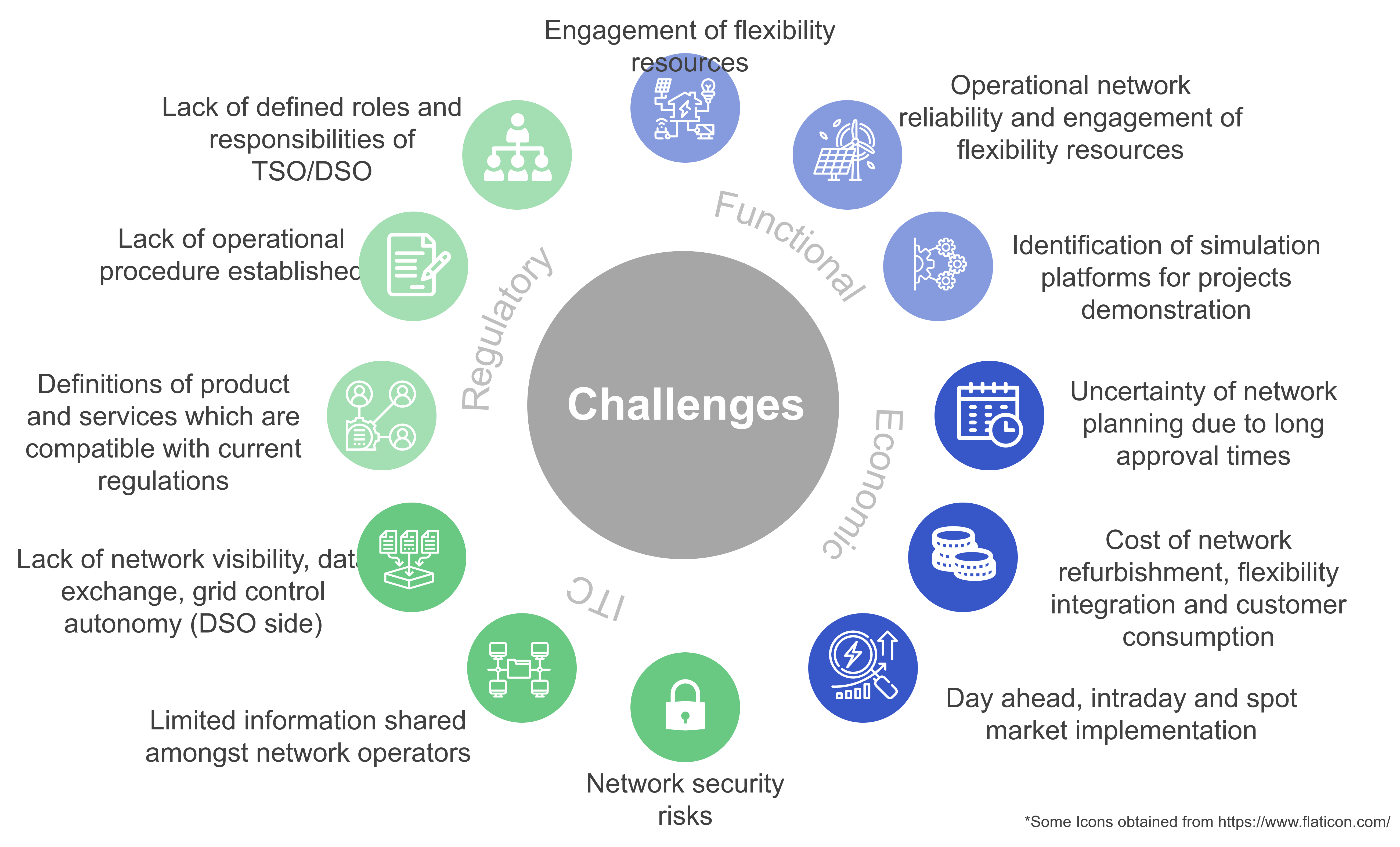
Challenges for the Interaction between TSOs and DSOs
Functional, economic, ITC and Regulatory challenges for the interaction between TSOs and DSOs.
Copyright: Berbara Herndler

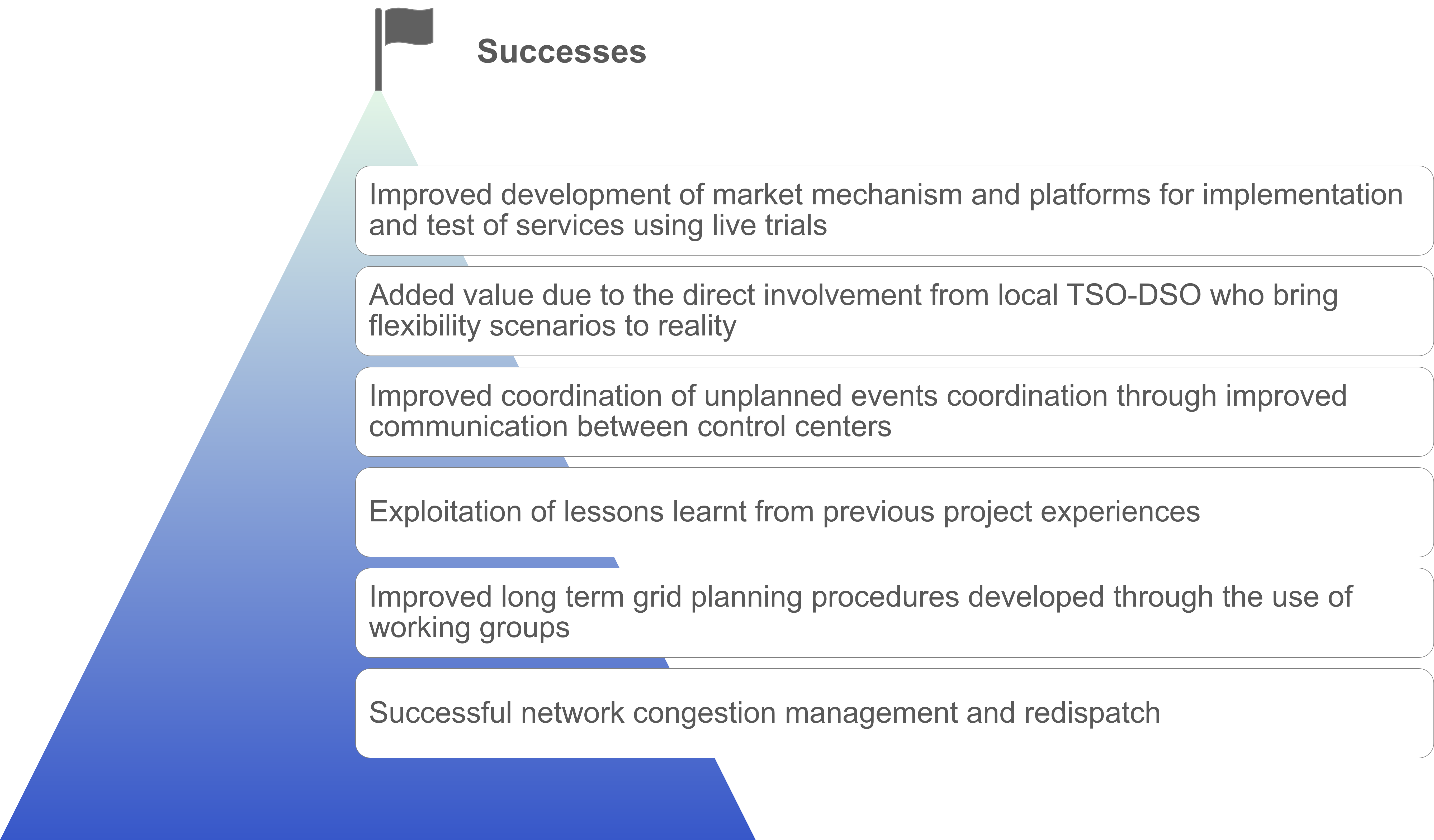
Success Factors for the Interaction between TSOs and DSOs
Success Factors for the Interaction between TSOs and DSOs.
Copyright: Barbara Herndler
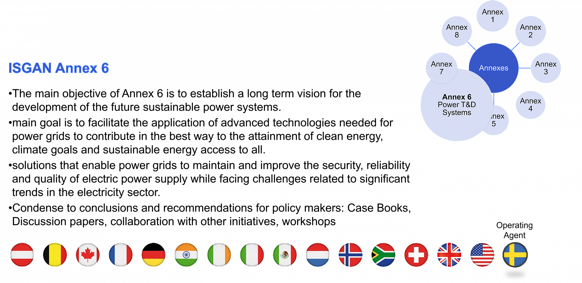
Description of ISGAN Annex 6
The main tasks and objectives of ISGAN Annex 6 are described and the participating countries (as of June 2020) are listed.
Copyright: Susanne Windischberger

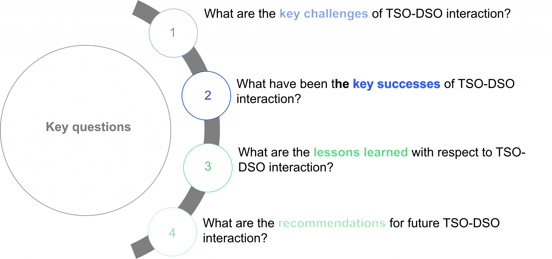
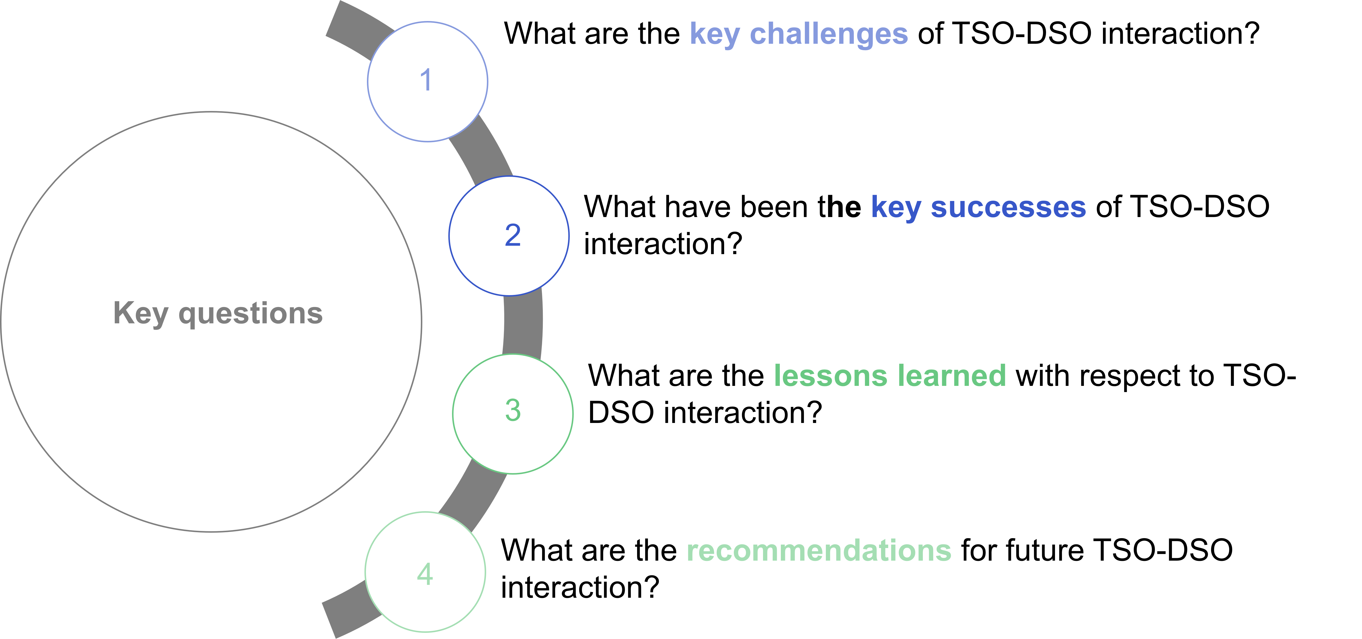
Key Questions for TSO-DSO Interaction
The most important issues for communication between transmission and distribution system operators are listed.
Copyright: Barbara Herndler
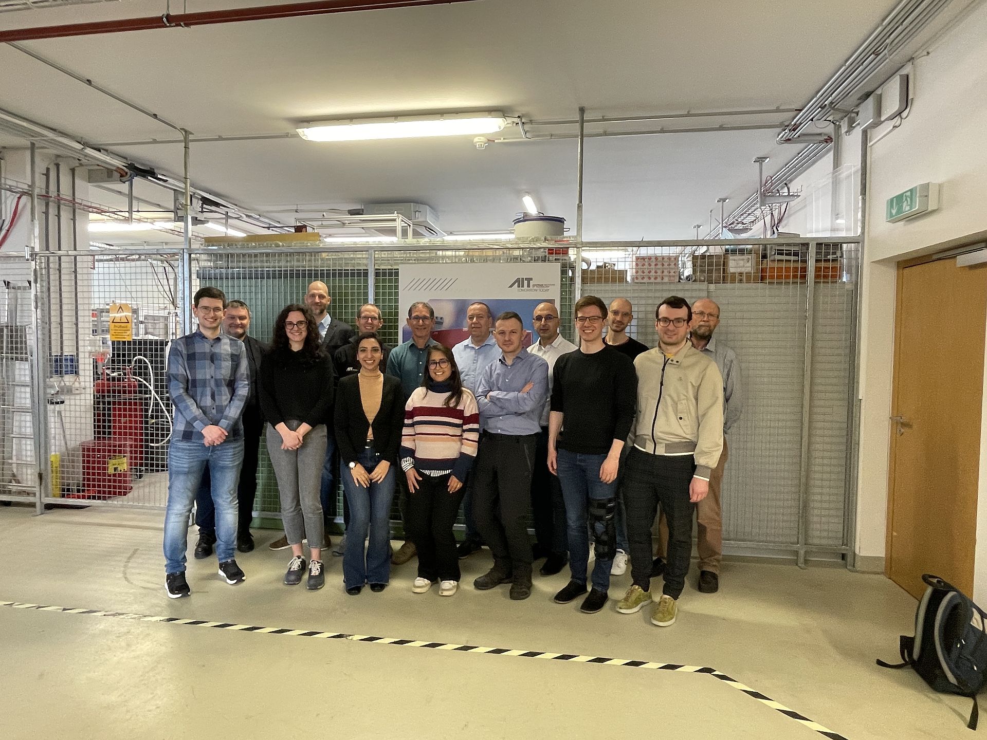
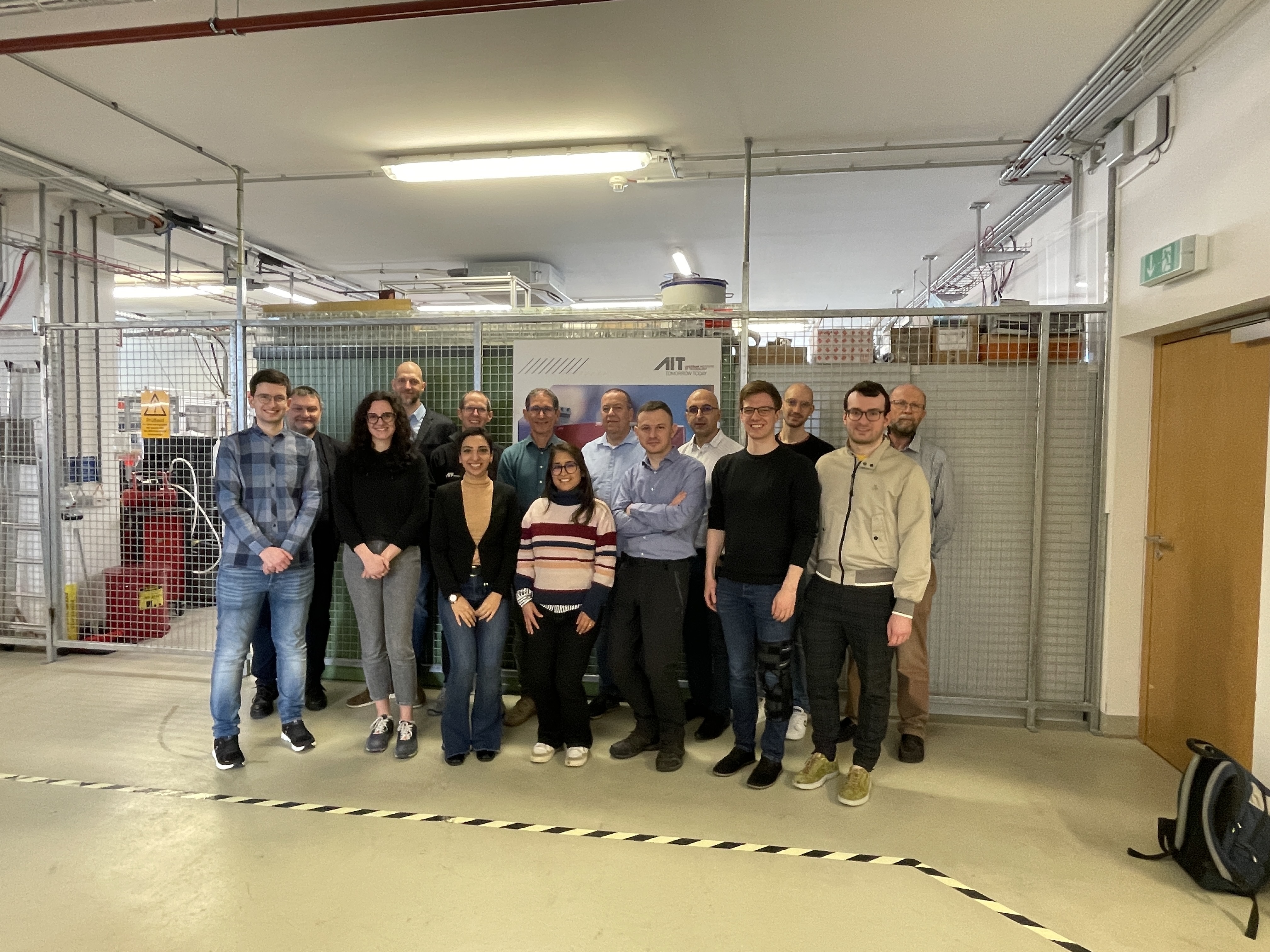
SIRFN-AIT Workshops "Grid-forming converters - testing and validation challenges" - March 2024
International SIRFN experts and participants of the SIRFN-AIT Workshops "Grid-forming converters - testing and validation challenges" visiting the laboratory showcase at the AIT MicroGrid Labor in March 2024.
Copyright: AIT Austrian Institute of Technology
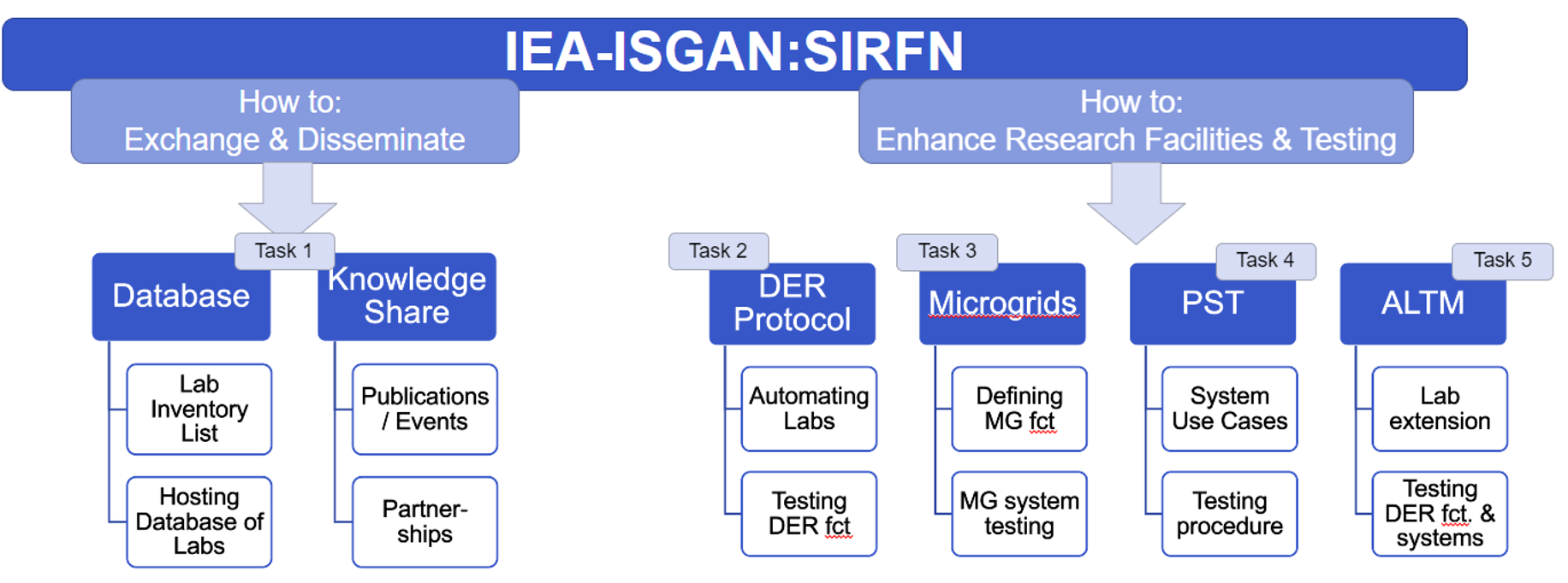
Organisation of the SIRFN network and technical topics in the project period 2021-2023
Overview of the organisation of the SIRFN network: The work programme for Annex 5 approved by the ISGAN Executive Committee (ExCo), the decision-making body within ISGAN, is divided into two sections, one dealing with the dissemination and exchange of knowledge and the other with the implementation of concrete projects for the further development of the research infrastructure.
Copyright: ISGAN-SIRFN
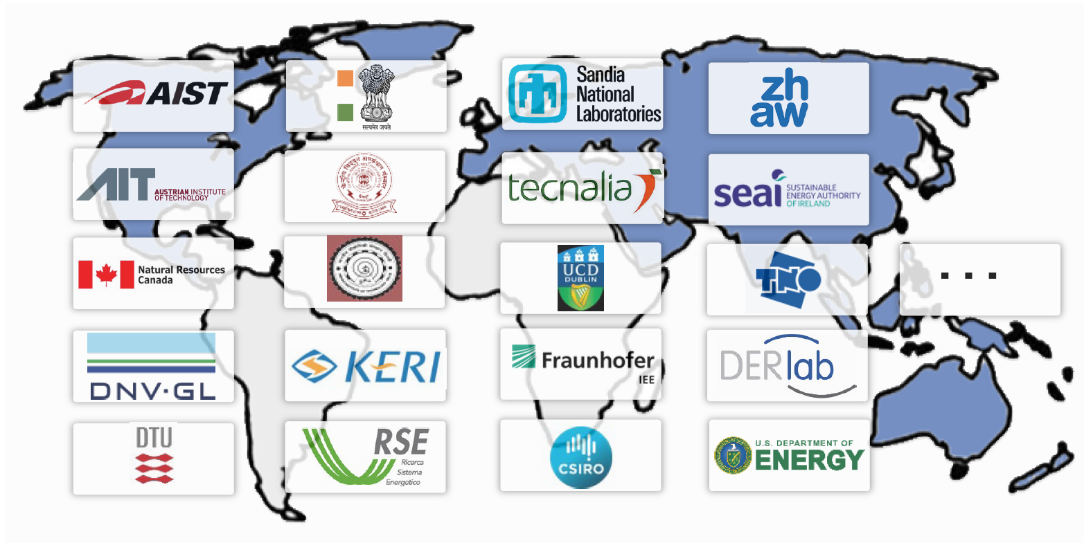
SIRFN member institutions 2024
Overview of the countries and research institutions participating in SIRFN 2024. SIRFN brings together leading research laboratories, academic institutions, industry partners and government organisations from around the world with the aim of promoting collaboration, knowledge exchange and the implementation of joint research projects.
Copyright: ISGAN-SIRFN
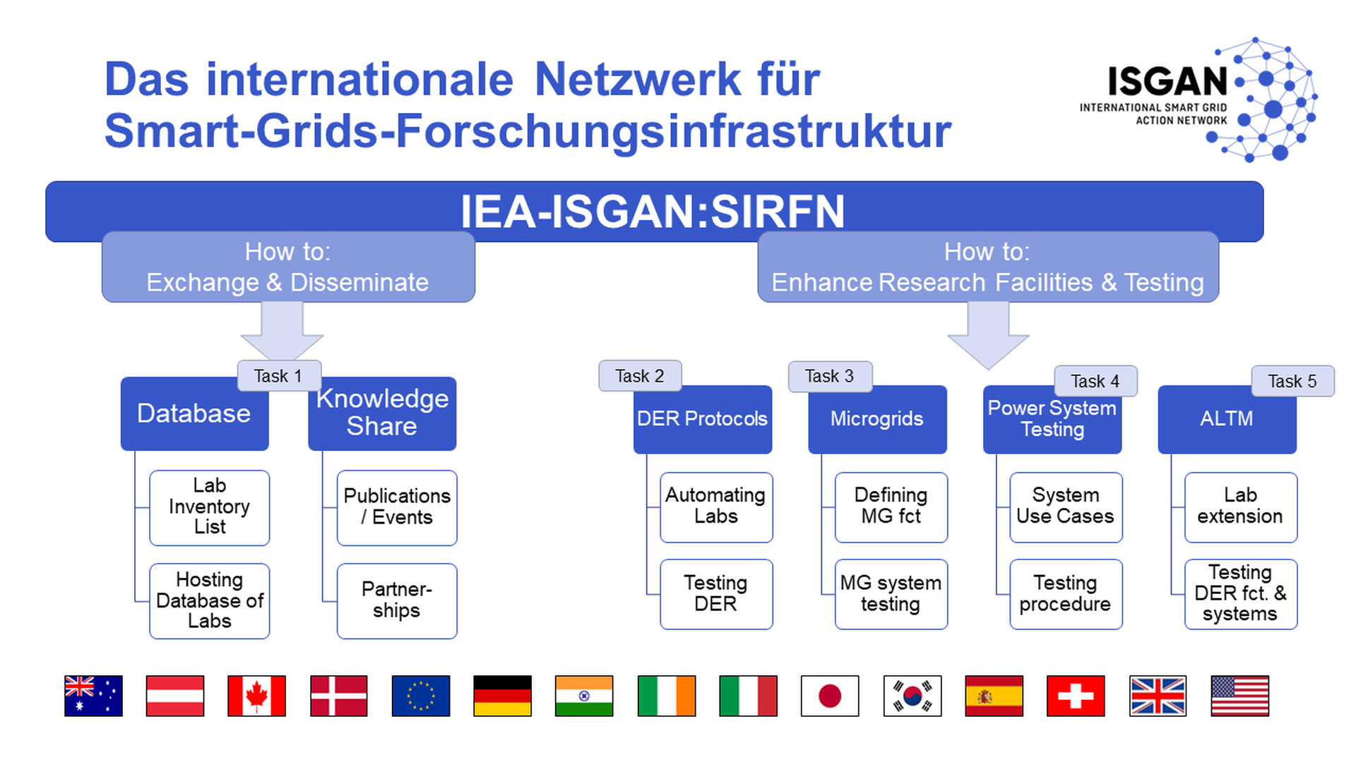
Organisation of the Smart Grids International Research Facility Network (SIRFN)
ISGAN Annex 5 is divided into two sub-areas dealing with the dissemination and exchange of knowledge on the one hand and the implementation of concrete projects for the further development of the research infrastructure on the other. The work is organised in the following main focus areas : - DER test protocols - Microgrids - Power System Testing - Advanced laboratory testing methods
Copyright: ISGAN Annex 5 SIRFN
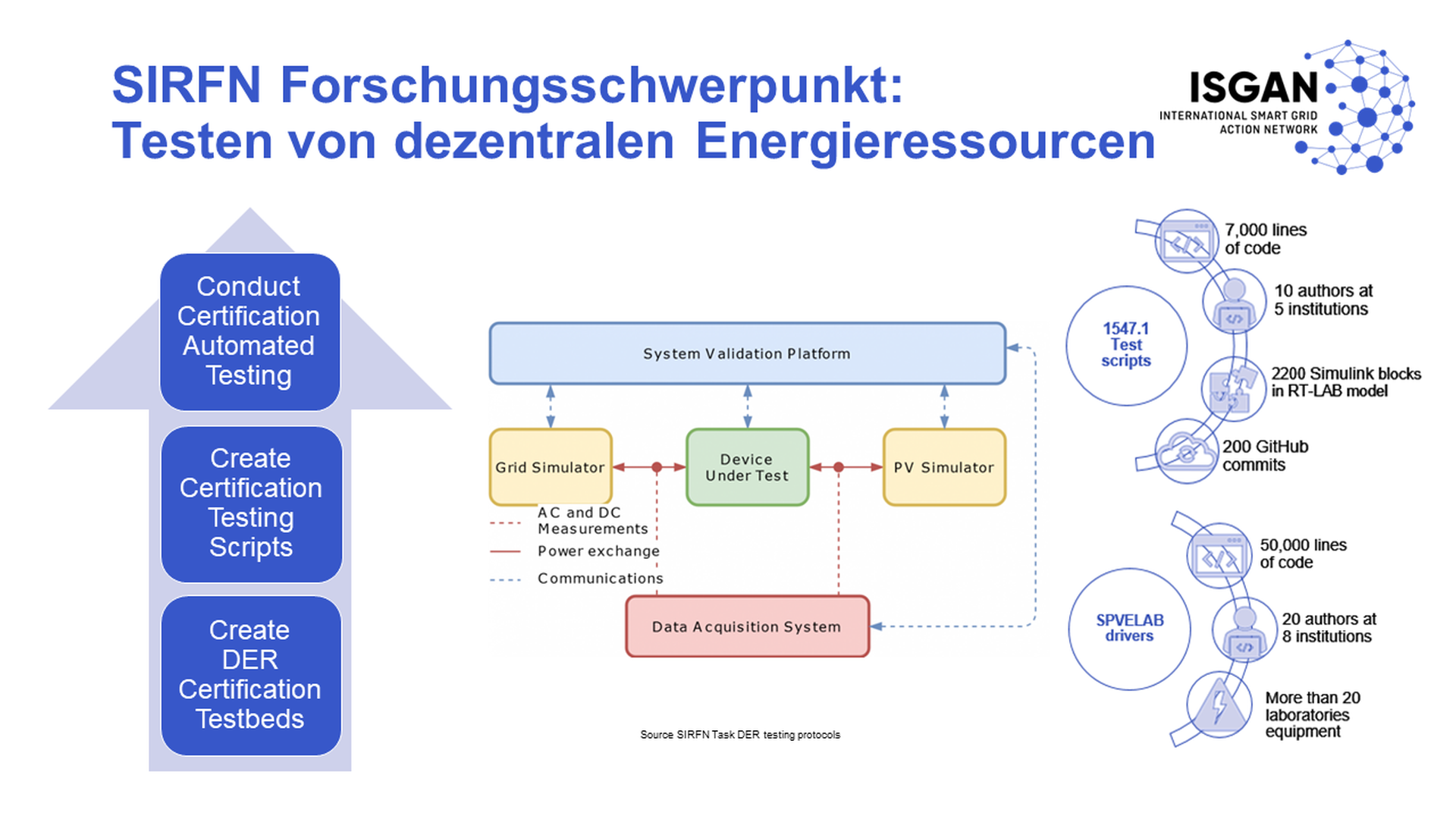
SIRFN Focus Area: DER testing protocols
As part of the SIRFN focus are, SIRFN laboratories are developing test protocols for validating the interoperability of distributed energy resources, which can be used in an integrated test platform (System Validation Platform), for implementing a harmonised, international certification standard for all distributed energy resources in the power grids.
Copyright: ISGAN Annex 5 SIRFN

SIRFN Focus Area Power System Testing
Within the framework of the SIRFN focus area "Power System Testing", leading international laboratories are pooling their activities with the aim of developing strategies for testing system aspects of digitalised, renewable energy-based, cyber-physical power systems.
Copyright: ISGAN Annex 5 SIRFN
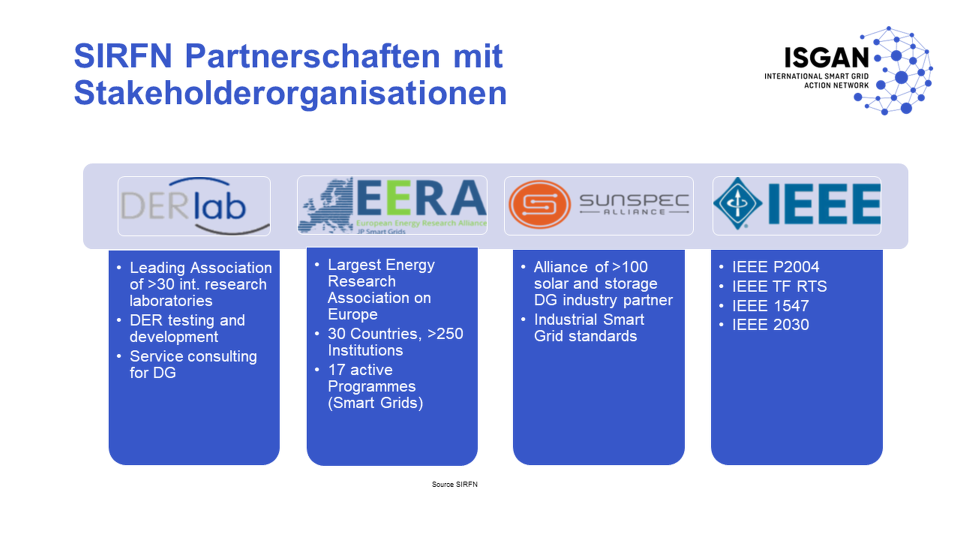
SIRFN Partnerships and Stakeholders
As a global network, SIRFN also works intensively with partners from other relevant networks. These networks include research and development, industry and, in particular, the field of standardisation.
Copyright: ISGAN Annex 5 SIRFN
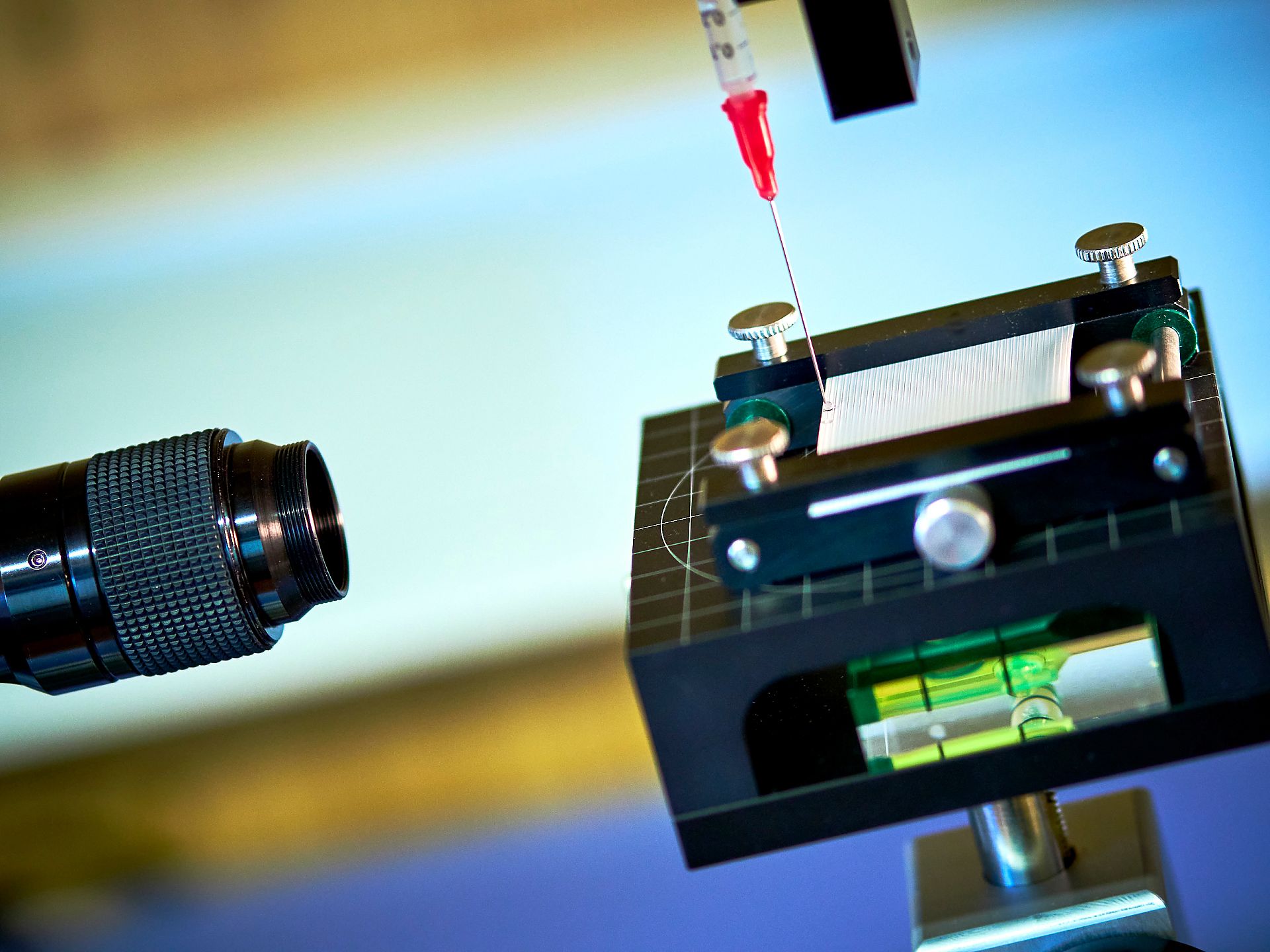
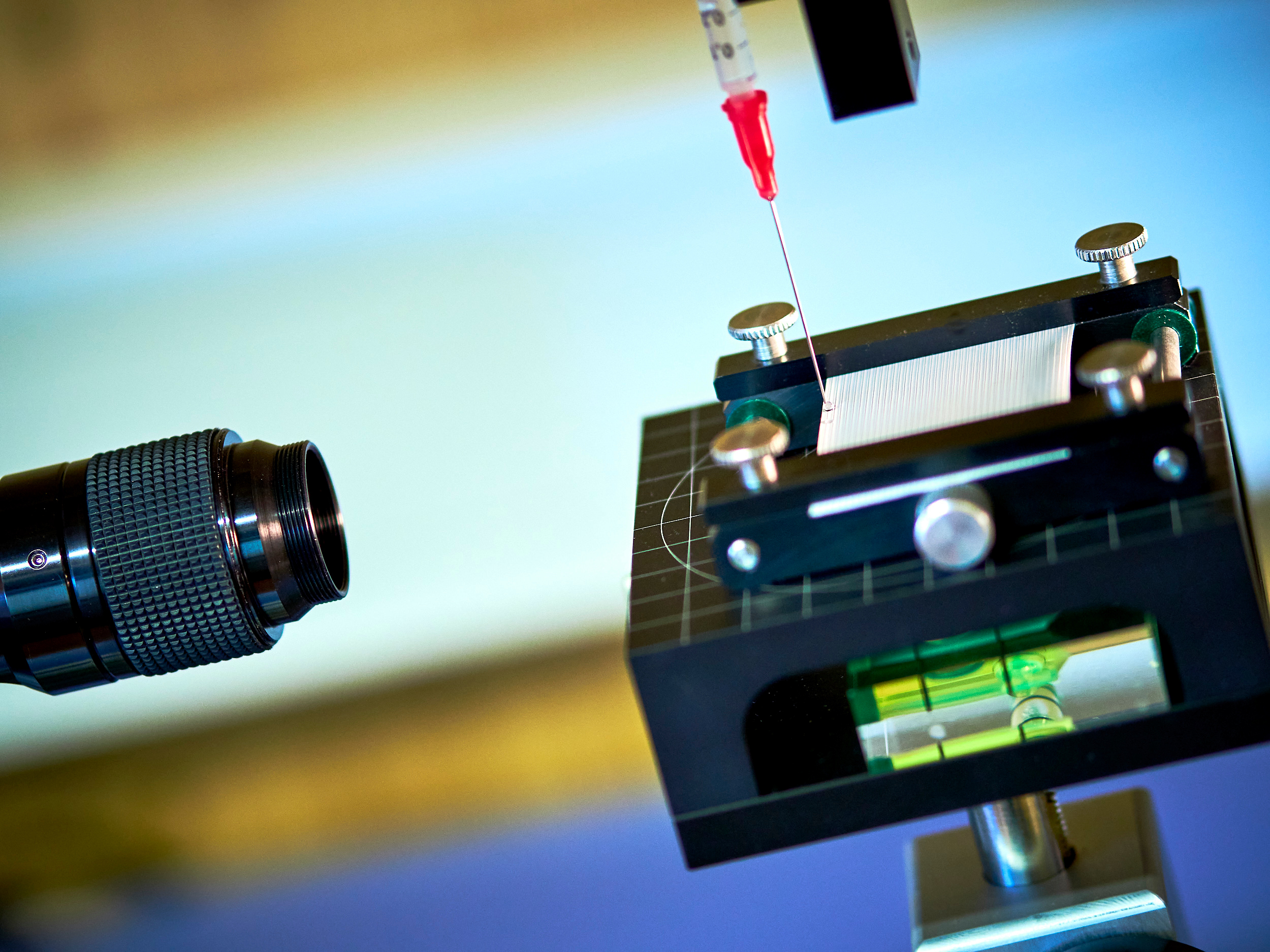
Contact angle measurement for membrane properties assessment
Depositing a drop of test liquid on the membrane.
Copyright: ACR/schewig-fotodesign
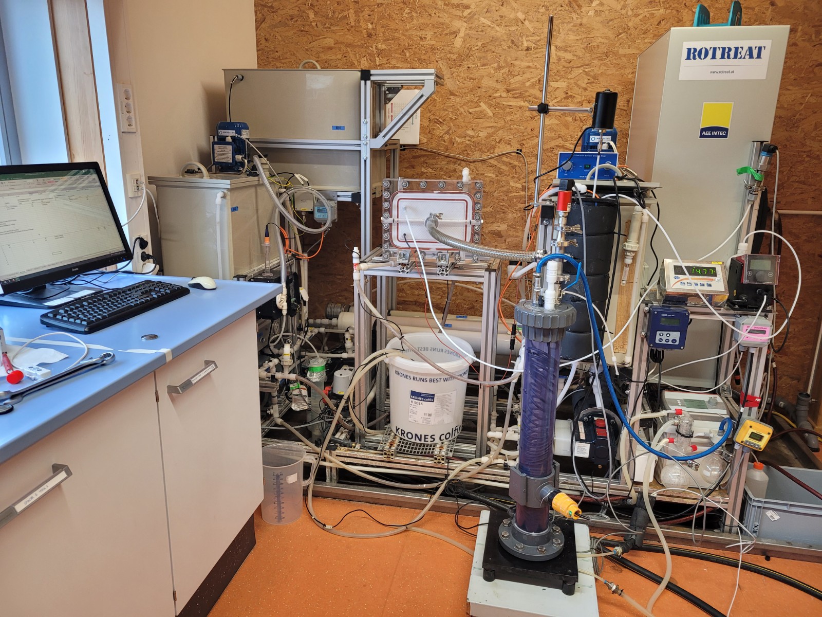
Membrane distillation (MD) laboratory plant at AEE INTEC in Gleisdorf
The MD laboratory system offers the option of connecting different module types and sizes, shown here with a connected test cell. The system can also be operated in different configurations, such as in direct contact mode or with vacuum.
Copyright: AEE INTEC
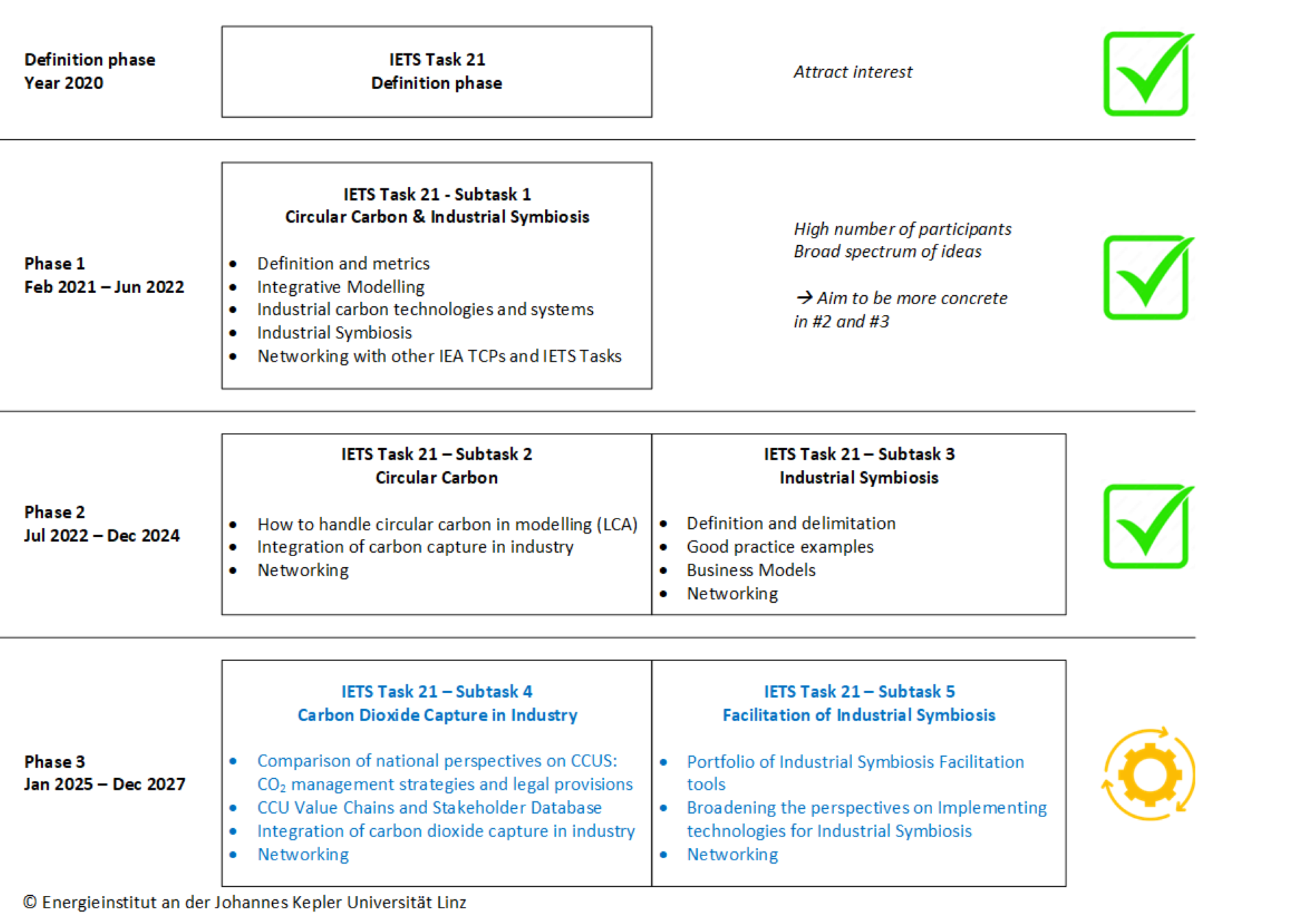
Overview IETS Task 21 Phase 3
The IETS Task 21 at a glance: A clear presentation of its development from its initiation in 2020 to Phase 3, including the activities of Subtasks 1 to 5.
Copyright: Eigene Darstellung: Moser, Energieinstitut an der JKU
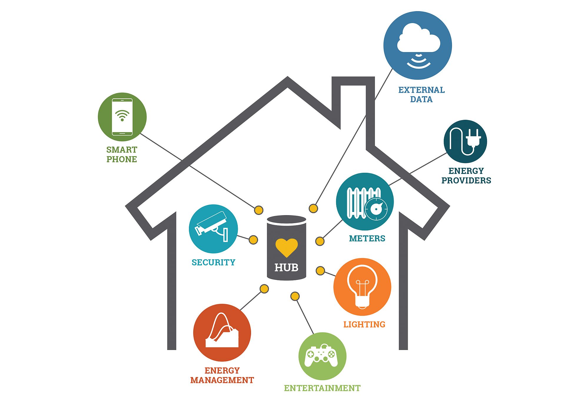
Smart home systems
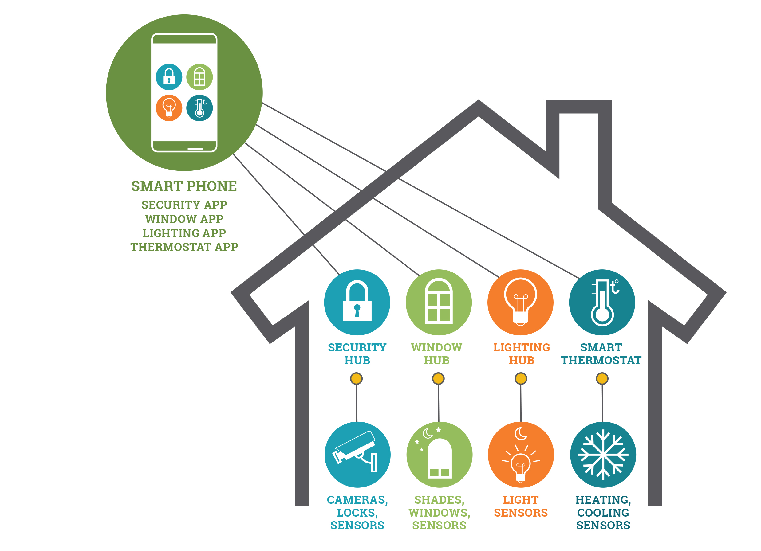
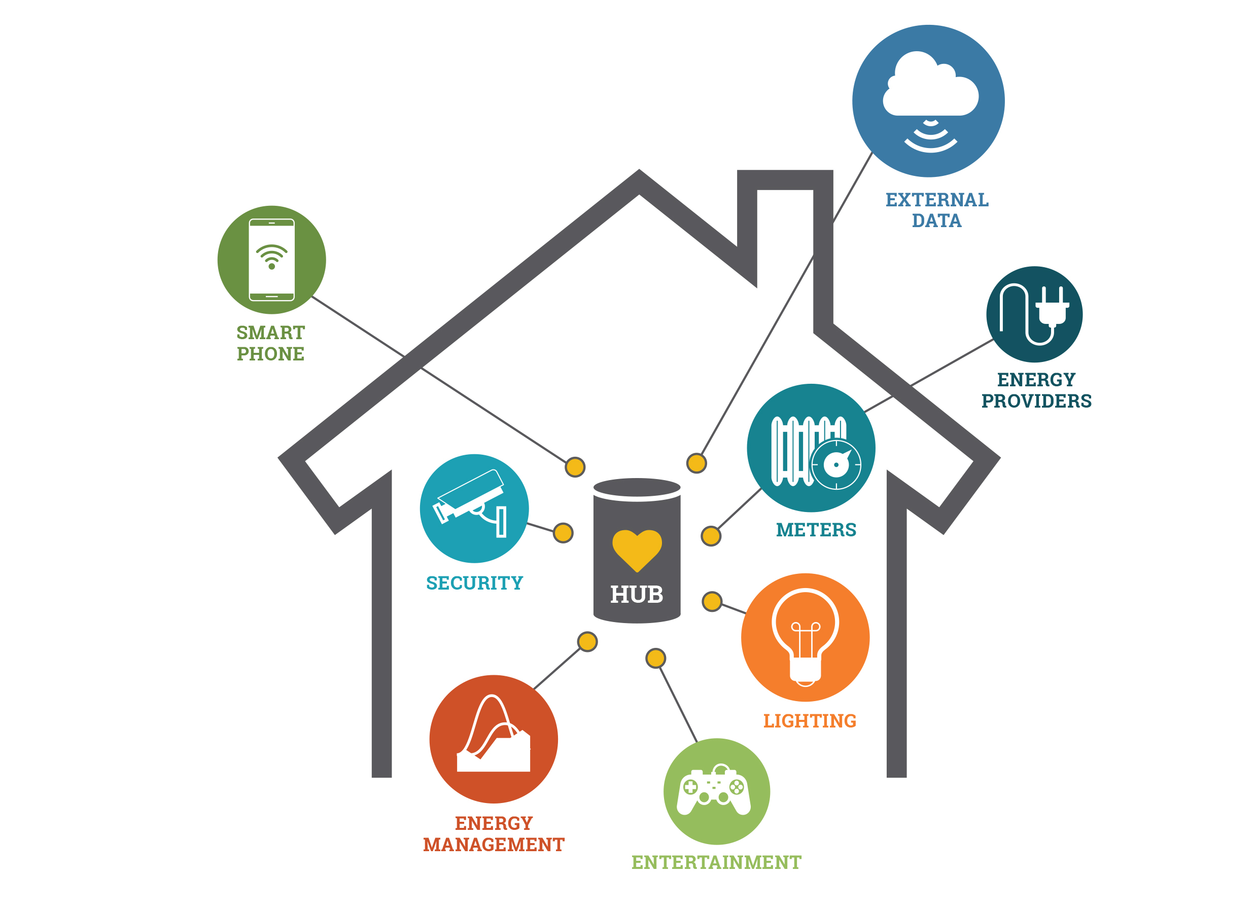
Smart home systems generally consist of sensors and switches connected to a hub (also called a gateway) from which the system is controlled with a user interface via wall-mounted terminal, mobile phone or computer, often via internet cloud services. Smart Homes utilize network connectivity to manage and automate services such as lighting, heating/cooling and washing. This has impacts on energy consumption (and running costs). EDNA investigates such impacts.
Copyright: IEA 4E Electronic Devices and Networks Annex - EDNA (https://edna.iea-4e.org/)
Smart home with multiple systems
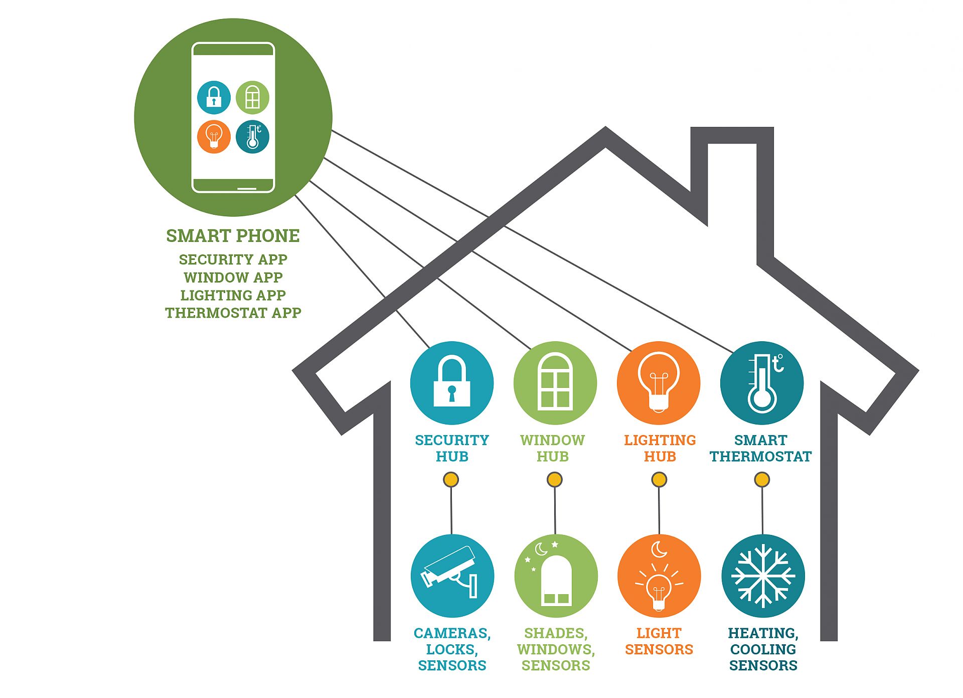
Smart home with multiple smart systems and interfaces, for example, smart meter display, lighting control display, heating and cooling control display, window status display etc. (This raises concerns about interoperability and acceptance by users).