Project Image Pool
There are 9 results.
Terms of use: The pictures on this site originate from the projects in the frame of the programmes City of Tomorrow, Building of Tomorrow and the IEA Research Cooperation. They may be used credited for non-commercial purposes under the Creative Commons License Attribution-NonCommercial (CC BY-NC).
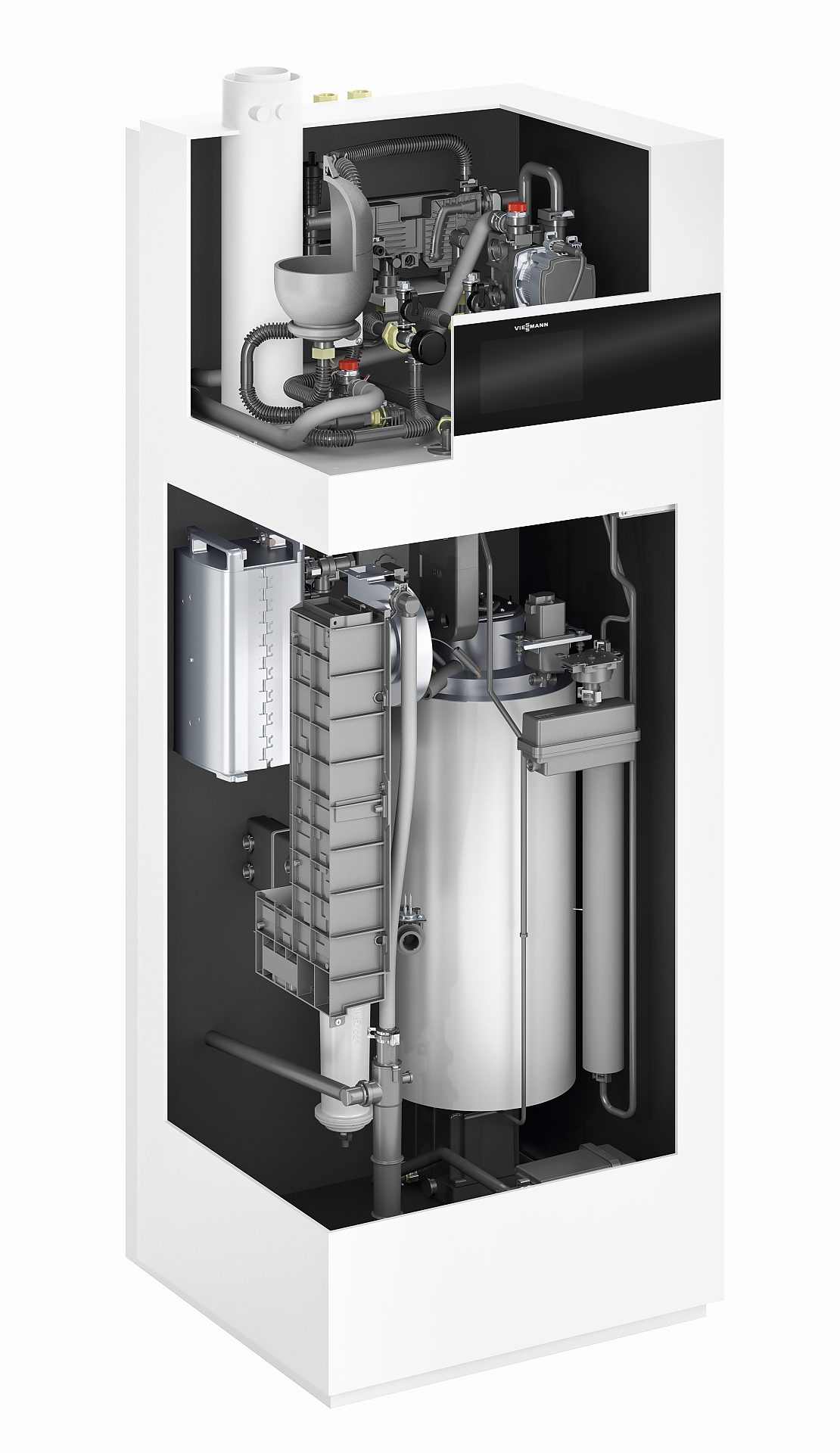
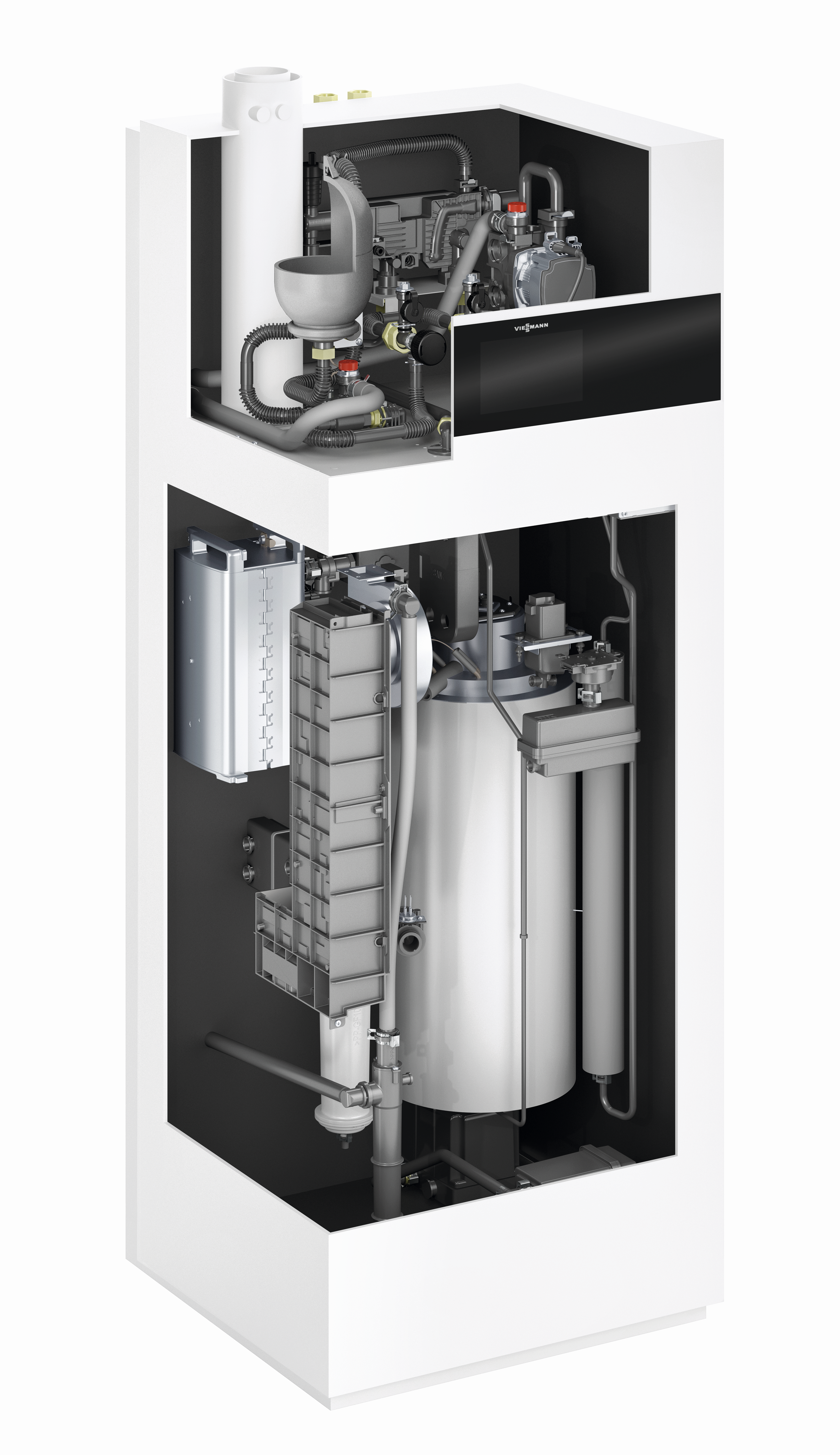
Inner structure of a fuel cell heating system
The illustrateion shows the inner structure and components of a fuel cell heating system.
Copyright: Viessmann Climate Solutions
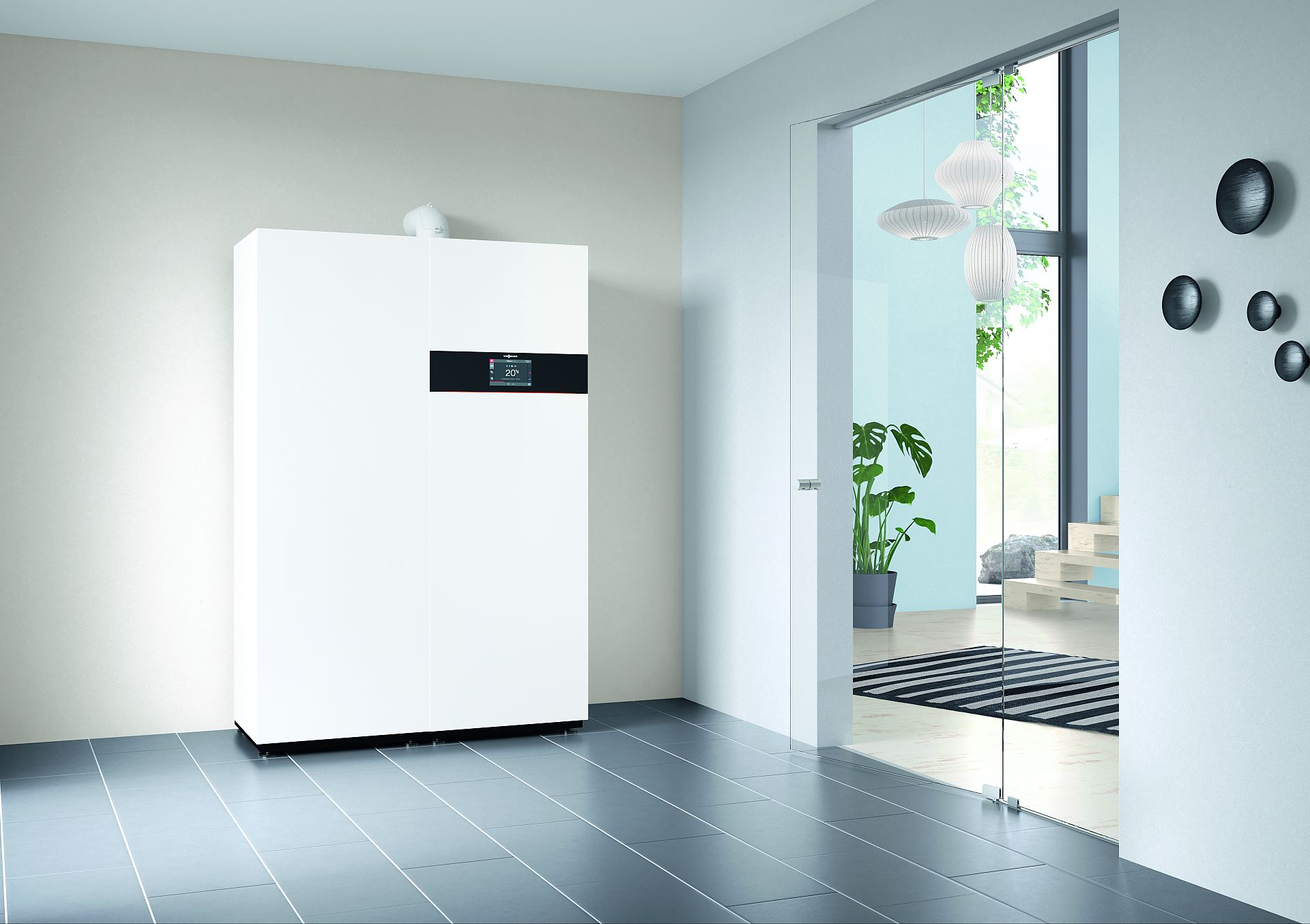
Fuel cell heating system Vitovalor from the company Viessmann
The illustration shows a fuel cell heating system from Viessmann company. This system is one of the best selling fuel cell systems in Germany.
Copyright: Viessmann Climate Solutions
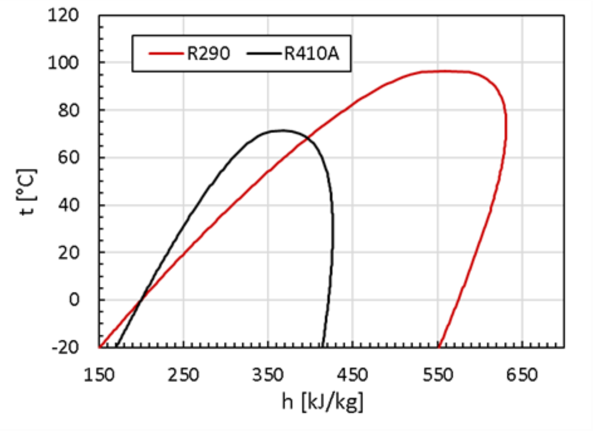
t/h diagrams of the refrigerants R290 and R410A
The comparison of the t/h diagrams of the refrigerants R410A and R290 shown in the figure shows the higher evaporation enthalpy of R290 and the difference in the critical temperatures.
Copyright: Institut für Wärmetechnik, TU Graz
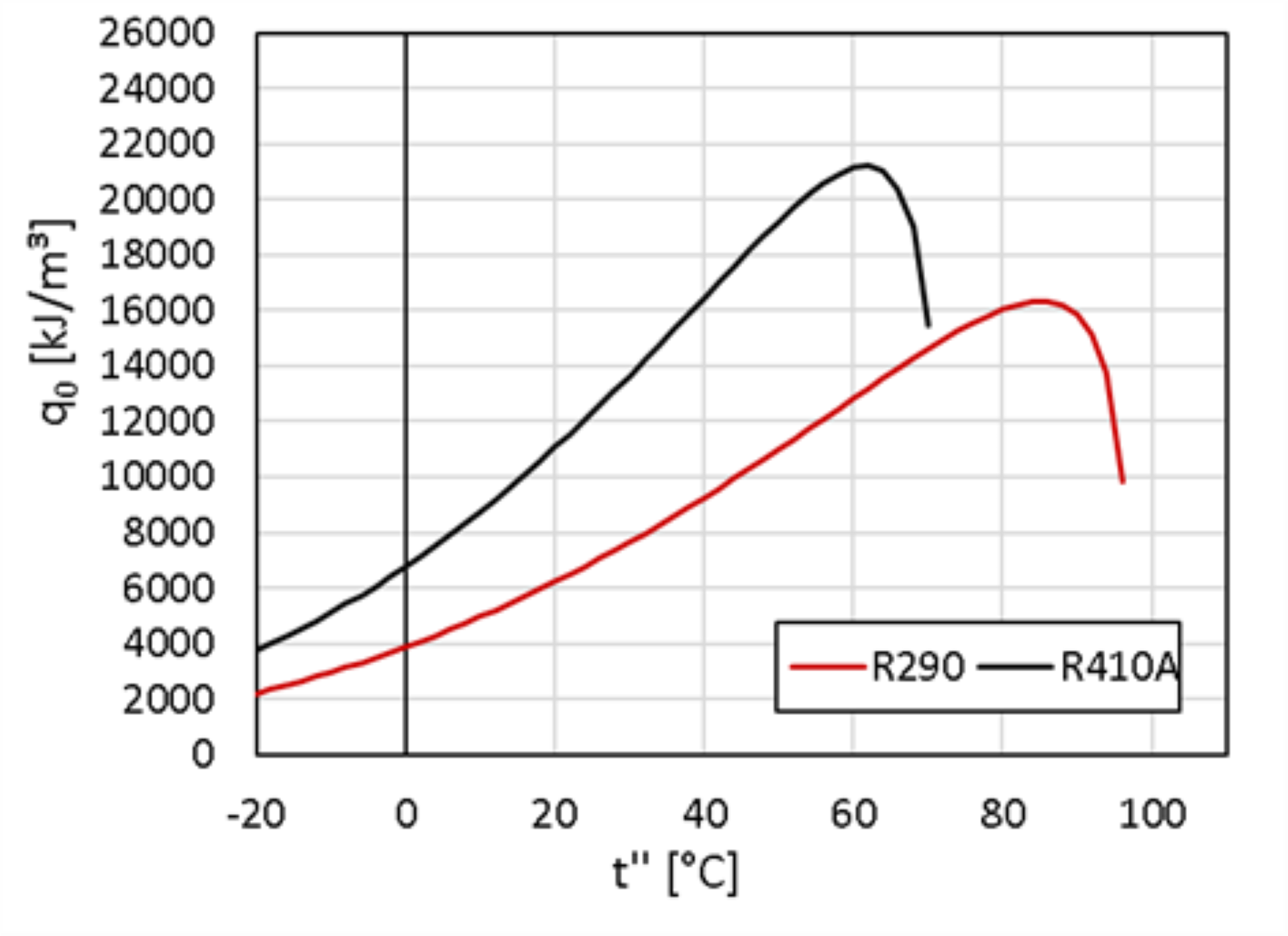
Volumetric cooling capacity of the refrigerants R290 and R410A
The figure shows the volumetric cooling capacity of R290 and R410A as a function of the dew point temperature.
Copyright: Institut für Wärmetechnik, TU Graz
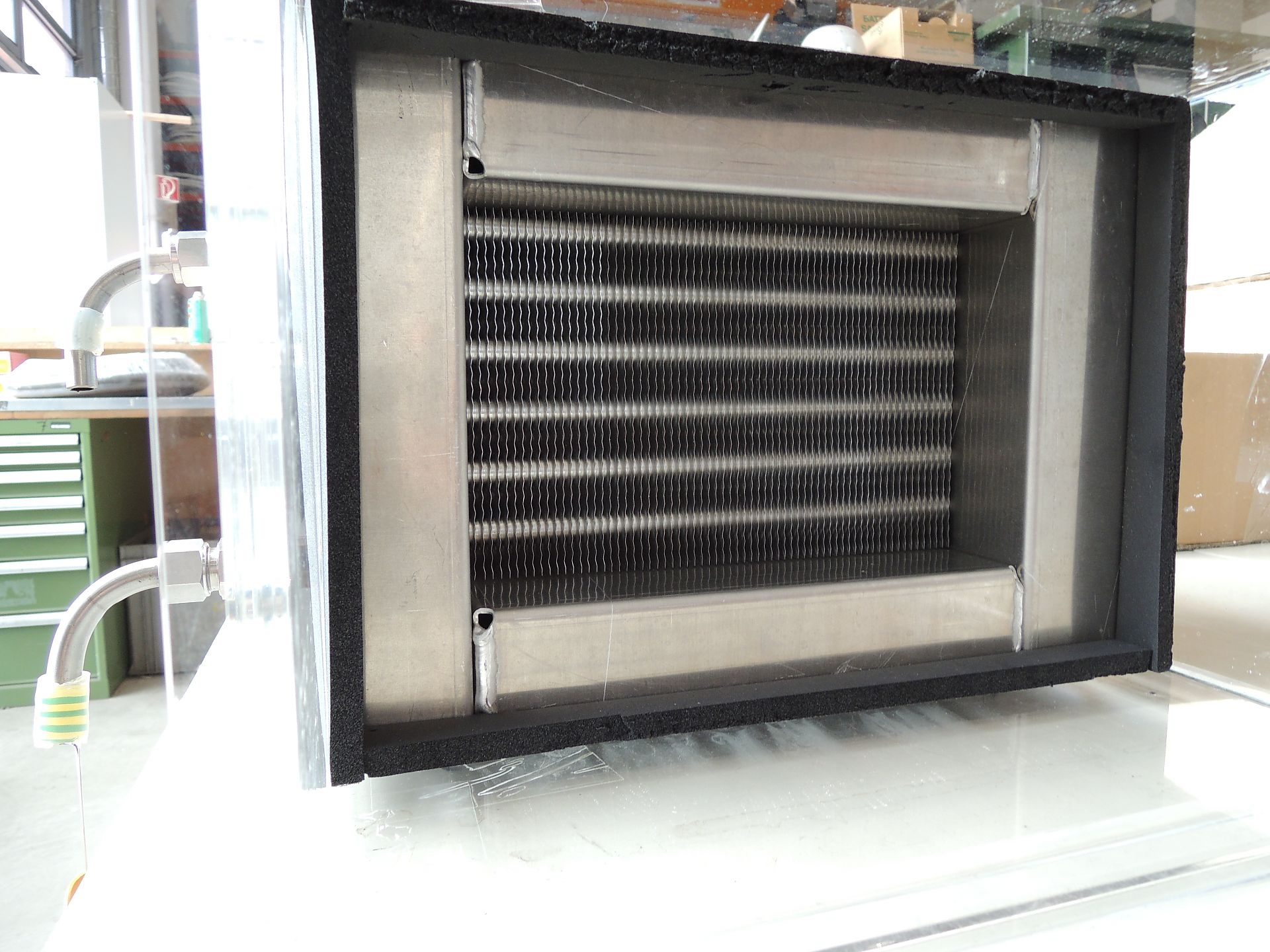
CTfin heat exchanger
Copyright: AIT Austrian Institute of Technology, Center for Energy, Sustainable Thermal Energy Systems

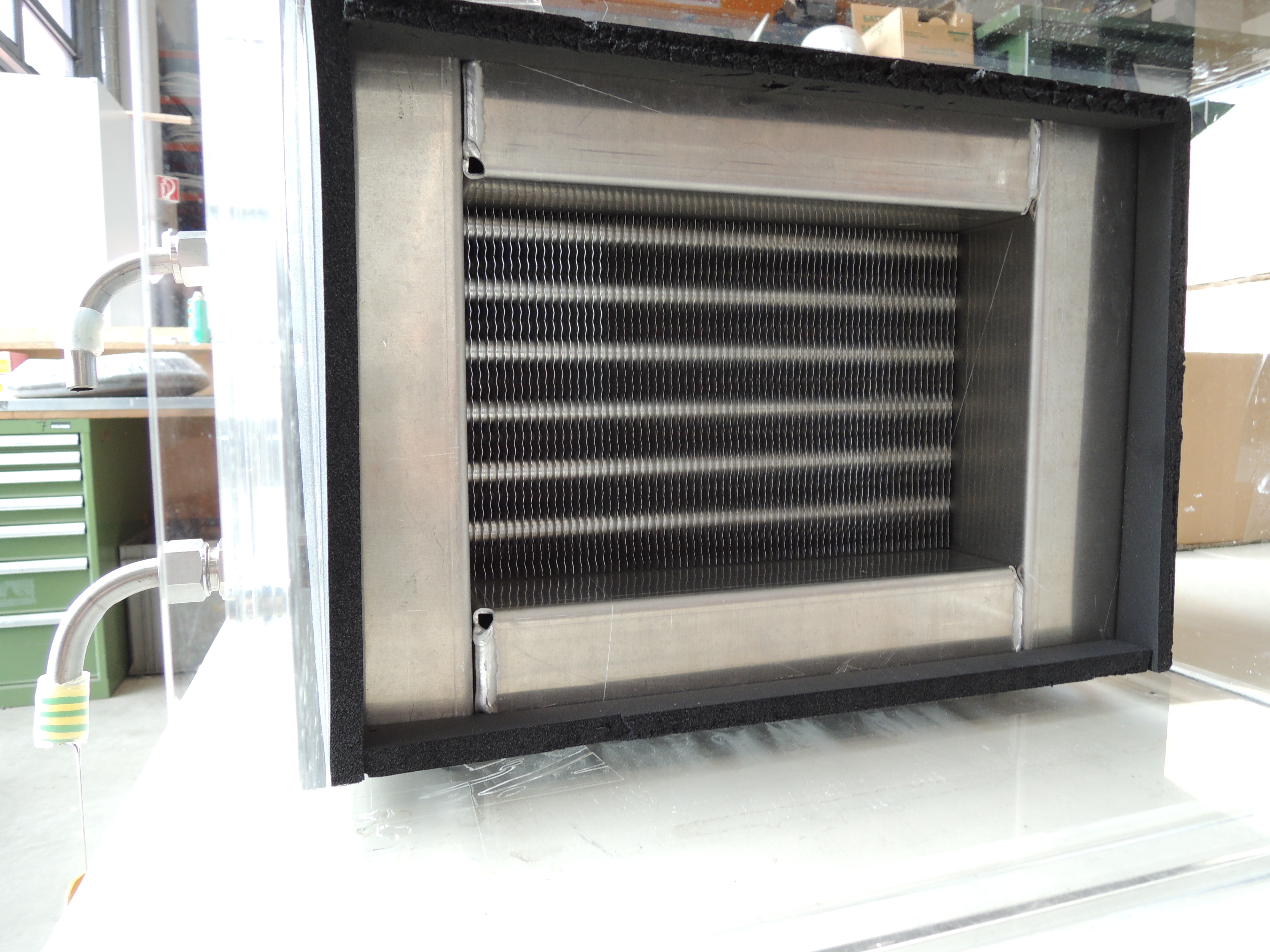
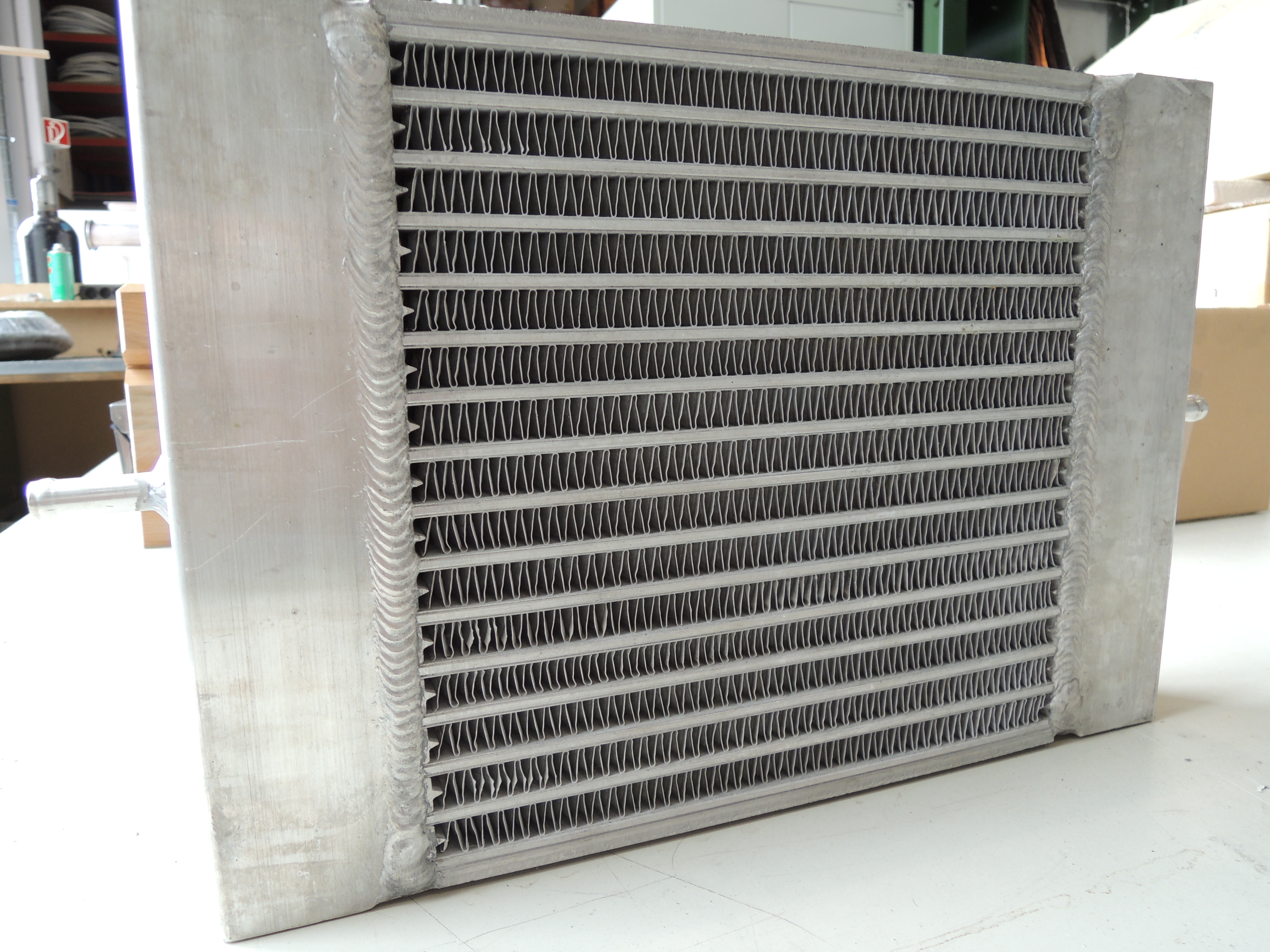
MPEfin heat exchanger
Copyright: AIT Austrian Institute of Technology, Center for Energy, Sustainable Thermal Energy Systems
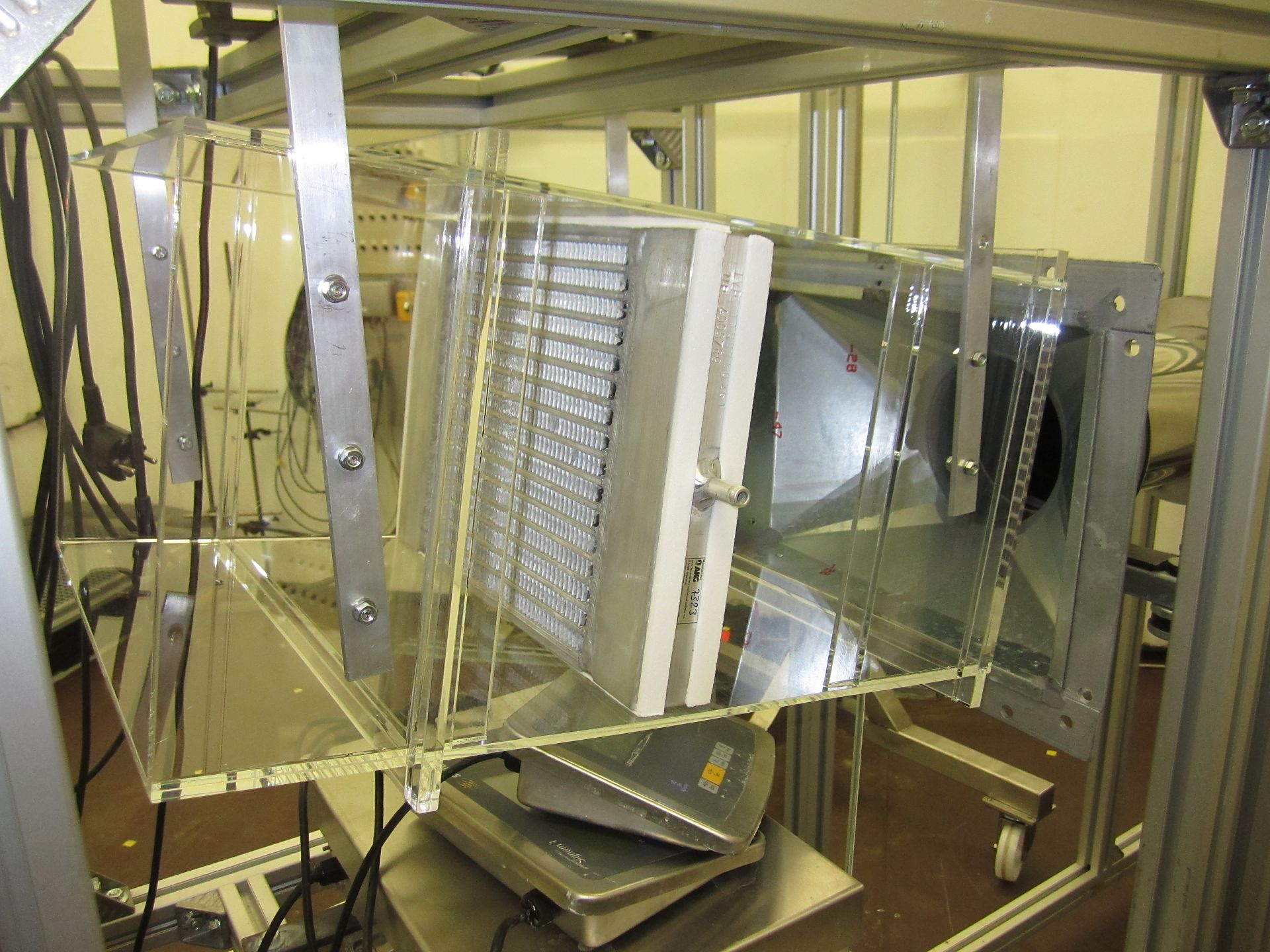
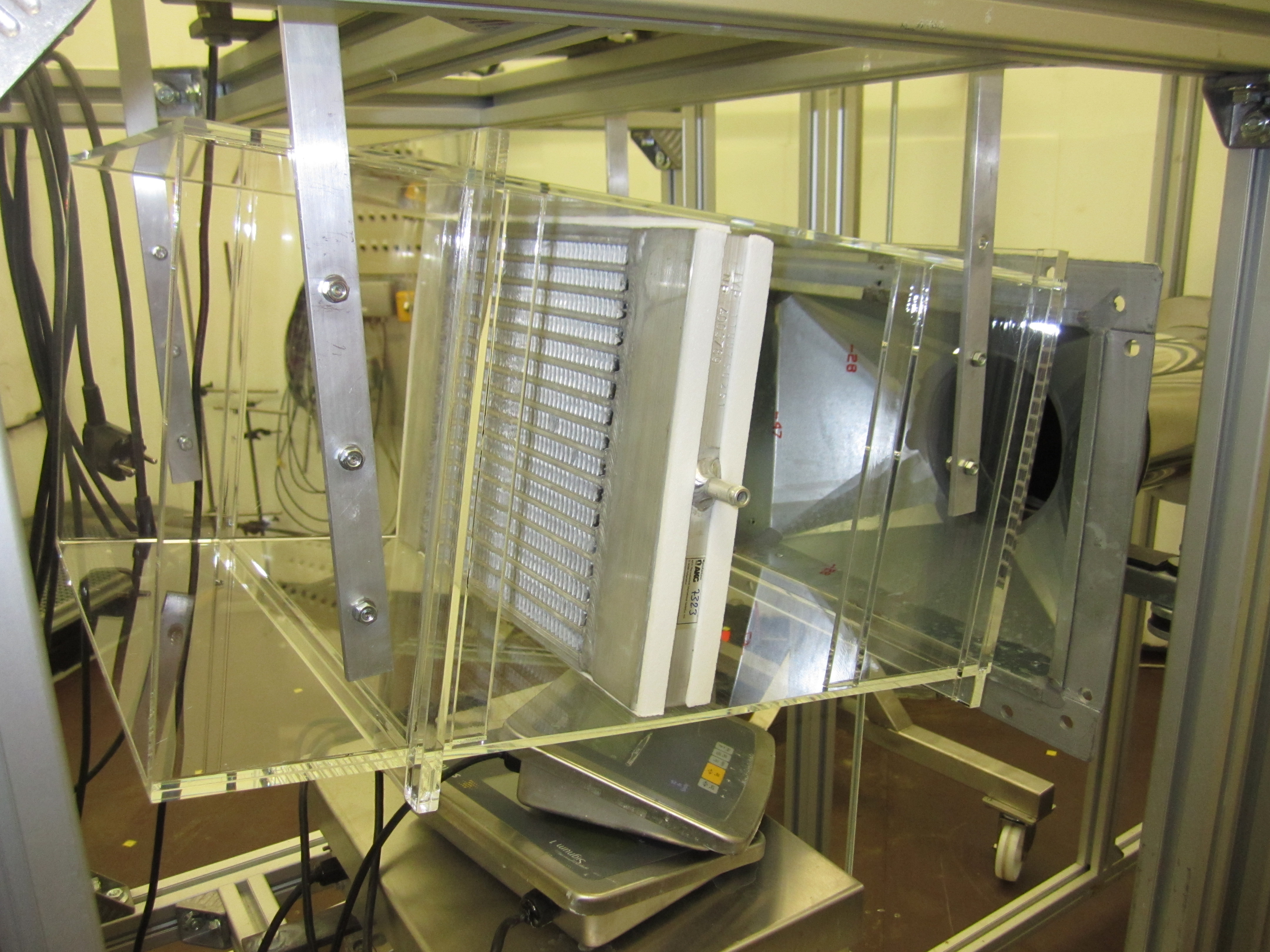
MPEfin Heat exchangers mounted in the flow channel
Copyright: AIT Austrian Institute of Technology, Center for Energy, Sustainable Thermal Energy Systems

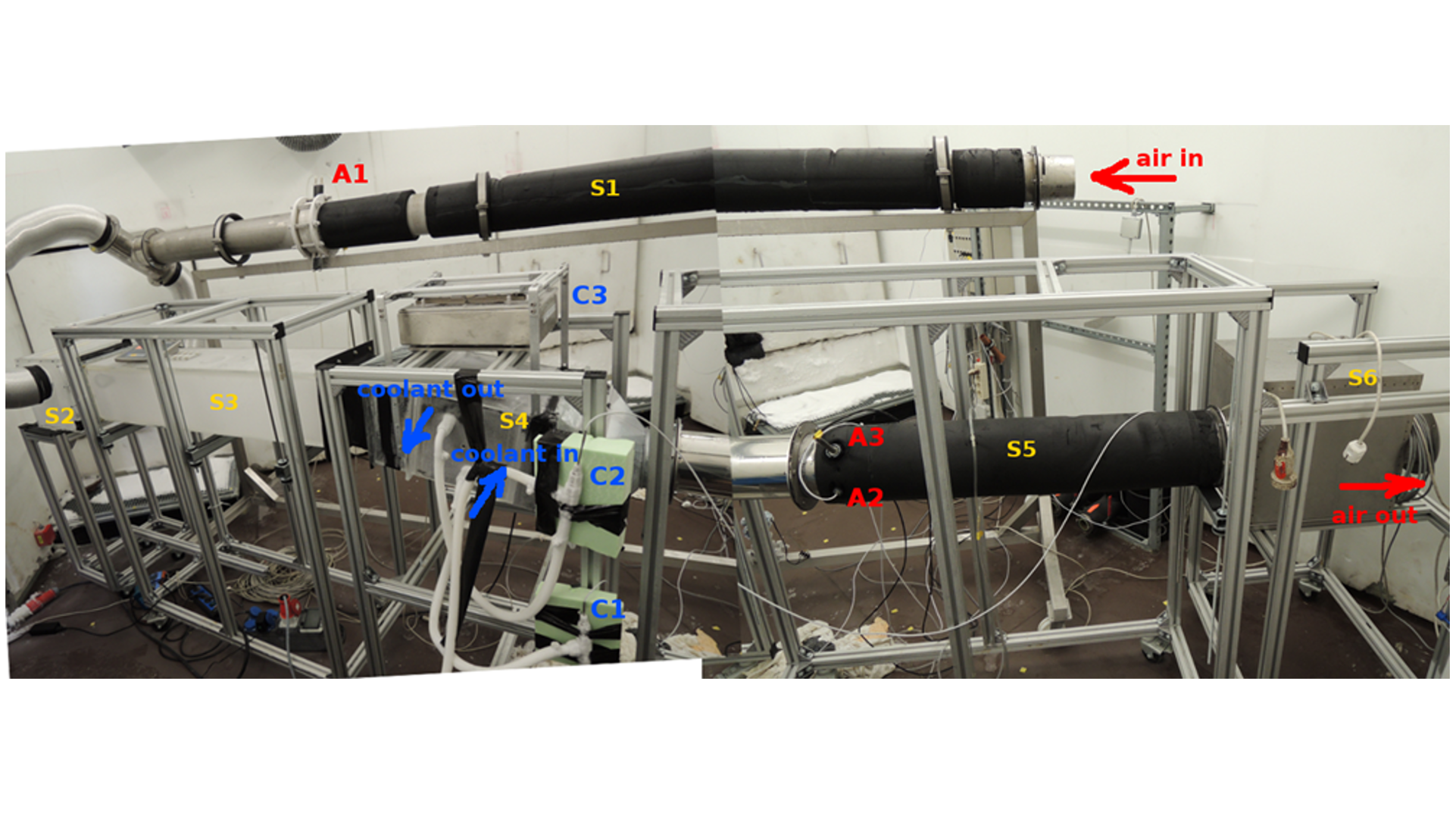
Experimental setup for investigating the frosting performance of heat exchangers at low ambient temperatures
Measurement sequence: in the initial phase the thermal mass of the heat exchanger is accommodated to the tempering conditions (A to B1), and then the main frost growth takes place (B1 to B2). Afterwards, the rapid change of the heat exchanger thermal state (at air flow rate curve steepest gradient) takes place (B2), and frost creation continues until the heat exchanger is fully blocked and the temperatures do not change any more (C).